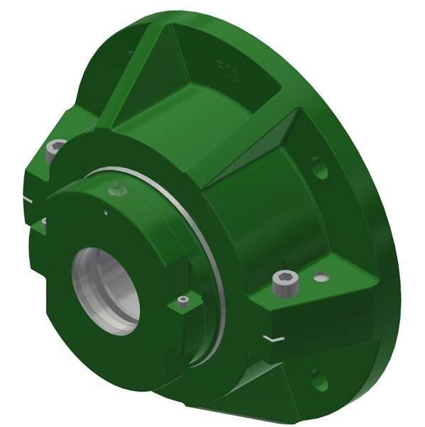
LSE315BRHFHTPS
📏 Dimensions on request
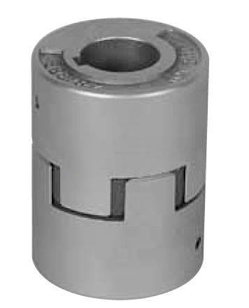
Custom & Special Bearings · Dimensions on request
| Brand | TIMKEN |
|---|---|
| Category | Custom & Special Bearings |
| Type | Custom & Special Bearings |
| Dimensions (d × D × B) | Dimensions on request |
| Weight | 1.67 lb |
| Catalogue Ref. | mcLDRacndt |
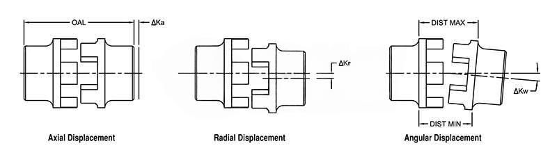
| Angular Displacement | 0.050 in |
| Bore Size | 1 1/8 in |
| Color | Metallic |
| Coupling Size | 28 |
| Coupling Type | Jaw |
| Cubic inches | 9.04397 in3 |
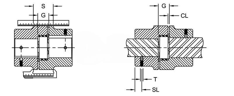
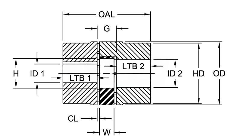
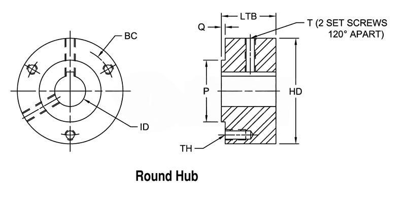
| Dimension G | 20.07 mm0.790 in |
| Dimension HD | 65.02 mm2.560 in |
| Distance between Spider and Hub Face (Dimension CL) | 2.54 mm0.100 in |
| Hub Material | Powder Metal |
| Hub Style | B |
| Keyway Size (W x D) | 1/4 x 1/8 in |
| Length thru Bore (Dimensions LTB1/LTB2) | 35.05 mm1.380 in |
| Max Torque (with 92 Shore A spider) | 1680.00 in·lb |
| Max. Angular Displacement (∆ Ka), n=1500 [1/min] | 0.90 o |
| Max. Axial Displacement (∆ Ka) | 0.0600 in |
| Max. Bore (Dimensions ID1/ID2) | 38 mm1.5 in |
| Max. Radial Displacement (∆ Kr) | 0.0100 in |
| Max. Speed | 8500.00 rpm |
| Max. Temperature Range (with 80 Shore A, 92 Shore A, and 95/98 Shore A spiders) | -50 to 248 oF |
| Min. Bore (Dimensions ID1/ID2) | 22.00 mm0.870 in |
| Nominal Torque (with 92 Shore A spider) | 840.00 in·lb |
| Normal Temperature Range (with 80 Shore A, 92 Shore A, and 95/98 Shore A spiders) | -40 to 212 oF |
| Notes | Maximum bore may be achieved through the use of a shallow keyway.Maximum bore refers to maximum straight bore with keyway allowed in hub.Outside Diameter is equal to Dimension HD for B style aluminum sizes: 19, 24, and 28.S = Solid hub with no boreSpider Outside Diameter (Dimension A) is equal to Outside DiameterThe values regarding displacement are provided assuming normal operating conditions (i.e. temperature, torque with nominal rating of the coupling, speed/RPM rating of the coupling, and misalignment). Careful installation (i.e. alignment) and periodic inspection should be provided to provide the optimum life of the coupling. Special consideration should be given as to the position of the shafts and the amount of axial movement the coupling will be exposed to. The more accurate the alignment of the coupling, will result in greater life of the elastomer. A coupling guard and rotating equipment safety procedures should always be followed. Please consult the Lovejoy web site at www.lovejoy-inc.com for assembly instructions of the curved jaw coupling. |
| Outside Diameter | 65.02 mm2.560 in |
| Overall Coupling Length | 89.92 mm3.540 in |
| Set Screw Style Coupling Location Size (Dimension SL) | 14.99 mm0.590 in |
| Set Screw Style Coupling Size (Dimension T) | 5/16-18 |
| Spider Outside Diameter | 65.00 mm2.560 in |
| Spider Thickness (Dimension W) | 15.00 mm0.590 in |
| Style | Bored |
| The Curved Jaw Design | Three piece design that is easy to assembleThe curved jaw design incorporates both radial and axial curvature (crowning) to the elastomer (spider)Hubs are offered in sintered iron, steel, aluminum, cast iron and nodular iron materialsThree different urethane elastomers availableNo metal to metal contact and no lubrication requiredFail safe design due to the jaw in compression design (continues to function after the elastomer fails)The CJ series covers a torque range of 67 to 247,800 in-lbs |
| Type | Curved Jaw Coupling Hubs |
📏 Dimensions on request
📏 Dimensions on request
📏 Dimensions on request
📏 Dimensions on request
📏 Dimensions on request
📏 Dimensions on request
📏 Dimensions on request
📏 Dimensions on request
📏 Dimensions on request
📏 Dimensions on request
📏 Dimensions on request

📏 Dimensions on request
📏 Dimensions on request